If you want to do code-CAD for anything substantial and you haven't yet developed a significant dependency on OpenSCAD, do your brain a favour and spend at least some time with CadQuery, Build123D or (if you prefer JS to Python) Replicad.
As impressive as NopSCADlib and BOSL2 are (and OMG they are, when you consider what they have to work with!), OpenSCAD is a one-way, declarative CSG environment that essentially only outputs mesh formats. It's really not that much better than working with three-dimensional pixels. You won't really be able to analyse, iterate over or measure your models, easily build on faces, do easy chamfers or fillets, export STEP files, make use of constraint-based designs, model assemblies, or so many other things that "CAD" means in the 21st century. All the tools that help you do this on OpenSCAD are layers and layers of task-specific hacks and clever bodges.
I totally get wanting to make models with version-controlled text files instead of GUI CAD (which can be a sort of weird battle to learn for a programmer), and I get wanting to avoid FreeCAD. I just don't really get wanting to limit oneself to such a limited concept of a 3D "model"!
The three alternative systems I mention are all based around bindings to (or in Replicad's case, cross-compilation of) OpenCASCADE, which is a bRep CAD kernel capable of much richer interactions. It is not without its faults, but arguably code-CAD spares you from some of the inscrutability that trips up FreeCAD's interactive model.
The learning curve required a paradigm shifted in abstraction. That was too much.
I just want OpenSCAD simplicity, but with modern programming language syntax.
I ended up settling with PythonScad. I was able to hit the ground running and leverage what I already know about python within a day.
It's new, but the author is extremely active and collaborative on github (https://github.com/gsohler/openscad) and reddit (https://www.reddit.com/r/pythonscad/). The author actually pushed for merging this into OpenSCAD mainline, but got gatekeeped out since OpenSCAD maintainers believed Python went against OpenSCAD's mantra of being 'secure'.
I recommend PythonSCAD to anyone that liked OpenSCAD simplicity in abstraction but feel handicapped by the lack of expressiveness.
> The learning curve required a paradigm shifted in abstraction.
This is true! And I think that brute-force simplicity of OpenSCAD is the appeal. I am still ultimately a CAD greenhorn but it got me started, and I don't blame you.
But I guess the point I am getting to is, that paradigm shift is where you really want to be. It's certainly where I think most competent programmers who want to really build in 3D should want to be.
Because it unlocks the ability to reason about the shapes you're creating, within the code that creates them. You can for example place a feature in the centre of a face of an object you just created, without having to recalculate the location of the centre of the face or the normal etc.
You can write code that is truly parametric with real encapsulations, and without a battery of variable definitions and calculations for every single element -- because you can reflect on what you've already made.
(You can also export STEP files to other packages, import STEP files and reason about/analyse those as objects rather than meshes.)
As someone who's dabbled a little bit with OpenSCAD, SolidWorks, etc:
> Because it unlocks the ability to reason about the shapes you're creating, within the code that creates them. You can for example place a feature in the centre of a face of an object you just created, without having to recalculate the location of the centre of the face or the normal etc.
I can definitely see the appeal of this; would it be possible to refit such capability back into OpenSCAD's model (even if it meant breaking some backwards compatibility)? Like, you're not just executing imperative "drawing" operations, but the models you've created become available as first-class objects to be further referenced & poked at?
> I can definitely see the appeal of this; would it be possible to refit such capability back into OpenSCAD's model
This is where my understanding gets weak, but I think the answer in a practical sense is no. Not with the way that kernel works. It could be somewhat modelled on top, but then you have a layer around the kernel doing essentially the whole task of a bRep kernel.
Thankfully I have been able to do what I want to do without learning the complexity that comes with Build123d etc.
Perhaps someday, but I havent had the need to get there thus far.
Also: Encapsulation etc was achievable with Python, which is something I already know. PythonSCAD checked all the boxes for me without the learning curve.
Another option in this space is using python to directly generate openscad code, which is a fun exercise to sort of quickly visualize simple recursive algorithms in a 3d world and play with tilings, space filling curves, etc. of course building what amounts to a transpiler will be fun for some, or a distraction, depending on how focused you want to be on the 3d part.
But openscad is a cool and minimal instruction set for such experiments, and doing this in a language with better meta programming support would be even more fun.
That is such a popular thing that back when I was maintaining the Shapeoko wiki there was a separate section for that sort of thing and it was hard to keep up:
I really hope that OpenPythonSCAD becomes standard and that it can harness all that energy and creativity --- in particular note that it is now possible to upload a design for sharing using it.
Whatever this is supposed to be criticizing exactly, is misplaced and doesn't matter, because they are right about the limitations of openscad and the real world problems that result from those limitations.
You will discover these problems while still green, and their report is corroborated by anyone else who has used openscad.
You could try it yourself and discover that what they said is true.
If you've tried to use openscad to model more than a cube, then you have run in to the limitations. If you have gone on to spend years building models in openscad, then you know even more limitations and problems than you did while "green".
Even people like myself who use openscad for as much as they can because they love being able to describe an open source model in about 1k of human readable, editable, parametric, gittable text instead of several megs of xml or binary, even we will say that this is all simply true. the more experienced you are, the more you know how true it is.
I will still call myself green because I will simply call myself green about almost everything as simple facet of my character, regardless how many years or how much work I've done with something.
Should such people not advise others on what they have learned? Do self-proclaimed experts largely give better advice than experts, or even mere practitioners, who don't like to self-aggrandize?
Regardless, in this case their statements were all sound. As someone who has spent a lot of time figuring out methods to get things done that a new user would not know yet, I have no notes on this greenorns opinions.
It is a reasonable point. I am a greenhorn in the sense that I've been learning CAD for my own somewhat complex, multi-part projects for three years. And I am not an industrial designer. Or a mathematician! (I am opinionated.)
The point for me is that, as a relative novice, I have got past some really important hurdles recently. So I can explain the benefits of getting past them to people who maybe don't know they are there.
I started off using OpenSCAD because it convinced me I'd be able to make something, quite quickly. My first two or three things were OpenSCAD things. It introduces you to stuff that isn't immediately obvious: the more complex booleans like difference of simple primitives, extrudes, lofts, sweeps, revolves. Great! I made things, I printed them, it was transformative.
(There's also quite a good thread library -- Adrian Schlatter's threadlib -- that I do want to say is very helpful and I learned a lot from.)
But it will likely hold back your development as a CAD user for even modestly complex things. Because you will never get access to the fundamentals of your objects -- the faces, vertexes and edges. Putting aside BOSL and the like, it leaves you stuck with a lot of increasingly complex maths, when if you could use the generated geometry you would not have to be. You would have much simpler operations relative to faces and edges.
This is why I said it would be worth spending at least some time with these tools. So you know what is out there.
This is not true anymore with PythonSCAD.
There is a mesh() function which can yield the points and triangles from any
Object. The User is free to modify these points and faces and finally create a new solid from it "polyhedron"
You could use this to skew your model in a fancy way by altering the point coordinates but it might be more difficult to alter on the triangles.
By "faces" I don't mean triangles. I mean the true geometry of the object.
Say for example a single six-sided die: six faces, twelve edges.
But this would be twelve mesh triangles, right? None of which individually represent a face -- and six of the mesh edges are not edges in the true geometry.
A rounded six-sided die might have 26 faces (including the curved edges, rounded corners). 48 edges between them. etc. But the number of mesh triangles and edges will vary according to the precision.
bRep kernels can give you the geometry information, not just the mesh information.
Triangles quite low level internal data.
mesh could output also 4 point polygons on occasion.
of course we can add an parameter to mesh to let pythonscad combine the faces as mush as possible(sub-faces are coplanar) and you would actually get 6 squares for a dice),
even polygon would accept faces with n points as input.
however, openscad does not have an internal B-REP kernel and you would have to rewrite the program to change that.
Conversely, what if I want to import STEP files and modify them?
You can make an almost perfect analogy with raster and vector image formats. They both have their niches; however: it's trivial to rasterize a vector drawing, but it's a ton of work to vectorize an raster image well.
So, all things being equal, it makes sense to start your designs at the 'high ground'.
bRep apps can handle and work with meshes (though it's probably not the most efficient way to work with them) but no, generally speaking extracting the real geometry requires redrawing them. You can get a long way by decimating meshes and using various tools but you're going to end up breaking the result down and partly redrawing.
Plasticity (the sorta-CAD-sorta-modeller app) has seemingly just added some logic to the recent version to help with extracting the true geometry from meshes. I want to like Plasticity but it's not enough CAD for me right now.
The amazing thing to me is that PythonSCAD is useful just for allowing access to variables and being able to write out files --- and it allows encapsulating those capabilities in "normal" OpenSCAD so that it is then possible to use them in a supporting tool such as:
To add, there's a new CAD kernal that is in slow development called truck [1]. Is is written in Rust and you script/make models in Rust. It doesn't have any geometric constraints though.
There was a very short attempt at starting to make a GUI for truck [2] but development has seemed to have halted. There was discussion and hype about this here a couple months ago [3].
On the contrary if you're a coder doing anything non-substantial and only rarely need to do some basic 3d modelling I would say definitely look to openscad!
I make models for my 3d printer just a few times a year. I find it much easier to get back into openscad than remember my way around a gui or wrestle with more advanced tools.
There's nothing I've not managed to make with openscad yet, though the things I have made are embarrassingly simple (yet highly functional).
You CAN get things done, but there is no getting around the fundamental problems expressed here.
All my models are about 50% variable declarations and 50% inscrutable equations to express the relationships between the values. Sometimes huge ternary stacks because the language doesn't allow variable changes, so you can't have simple if/else/case to have a simple concept like a default value that maybe gets replaced based on some other condition.
And the lack of things like fillets is simply impossibl. The things you have to do to attain the end result of a fillet without an actual fillet function is ridiculous, and even after doing the ridiculous things, you still have a limited crap result where no matter what you simply can't actually have a fillet wherever you want, but you can compromise and get at least the ones you really need if you're willing to live with a simple design.
That is not a good tool. A good tool gives you the means to express whatever you need to express. Openscad gives you the power to express cubes and spheres and hulls and intersections of those, and even that only in a bafflingly limited way thanks to the language limitations.
It's not a great tool. It's a great proof of concept for a great idea for a great tool.
> There's nothing I've not managed to make with openscad yet, though the things I have made are embarrassingly simple (yet highly functional).
It is workable if you have an extremely solid grasp of mathematics, and you don't mind objects that ultimately retain the feel of the combination of a few CSG primitives.
But I make 3D-printed things that for a variety of reasons are little more than rings, plates, discs, and helixes, and I've already very clearly run into situations where the face/vertex/wire model of a proper CAD package is more or less the only way to keep control over a design.
The main complaint I have with CadQuery et. al. is the API verbs are all coming from the point of view of describing bRep shapes instead of thinking about the design from the standpoint of "how would I make this?".
I think there's an opportunity for a code-first CAD API to incorporate GD&T and manufacturability information directly as part of the modeling process. For example, if I'm making a shaft I want to describe that operation as it will actually be performed in the shop e.g.:
  (1) select round stock of nominal dimension X
  (2) cut to rough length
  (3) chuck in 3-jaw chuck and drill center
  (4) flip around in 3-jaw chuck and drill the other center
  (5) mount between centers
  (6) turn to rough outer dimension
  (8) turn down to add the various bosses, threads, chamfers, other details, etc...
With this kind of a process I get all kinds of GD&T information for free--for example, the precision of my 3-jaw chuck determines how much larger my nominal dimension X needs to be than my target rough outer dimension to be able to reliably achieve it.
So I think these APIs are coming at the problem from the wrong point of view--they're all about driving the CAD kernel and telling it how to draw abstract shapes in a computer. Instead what I want is to tell the computer how I intend to make the thing and get an estimate of what the result will look like.
> So I think these APIs are coming at the problem from the wrong point of view--they're all about driving the CAD kernel and telling it how to draw abstract shapes in a computer. Instead what I want is to tell the computer how I intend to make the thing and get an estimate of what the result will look like.
I have certainly learned over time that when you're looking at an object that exists in the real world, one way to start to figure out how to model it is to figure out how it -- or its injection-mould positive -- was physically made. Can it be cut with a mill? Was it glued together in parts?
It absolutely is fun to try to work out how to come up with a shape subtractively from some giant primitive as if it was a block of steel. I often find myself visualising in terms of a scroll saw. I watched a couple of great videos about three-dimensional scroll-saw work and it weirdly affected my understanding of CAD!
The problem of course is that that limits one to straight lines and arc moves.
Are there any really good G-code previewers for lathe work?
For that matter, what is the best 3D G-code previewer which will allow one to see the surface of the cut part in 3D? I'm about to break down and buy tkcnc --- is there something better?
No, I think G-code is too prescriptive and low level for the modelling task. What I'd prefer is some way to specify operations in a fluent, object-oriented API e.g.:
I can see where you are coming from, and I've thought about similar ideas. But ultimately, I think this fails for separation-of-concern reasons. Describing the part is different from describing how to make the part. The same part might be sent to 3D printing for a non-functional fit prototype, sent to a prototyping machine shop to make 5 or so units on basic CNC machines that require 3 set-ups to complete it, and after a few design iterations scaled to production on a multi-spindle Swiss-style lathe that drops finished parts into the basket all night long, lights-out. Those are wildly different programs and work flows.
Something like you propose might be an interesting thing to explore for creating CAM posts. The actual Gcode that your API would emit is going to vary quite a lot even within super-similar machines -- a 3+1 axis job targeting a machine with a FANUC controller is going to be pretty different from the same job targeting a machine with a Heidenhain controller.
> Describing the part is different from describing how to make the part. The same part might be sent to 3D printing for a non-functional fit prototype, sent to a prototyping machine shop to make 5 or so units on basic CNC machines that require 3 set-ups to complete it, and after a few design iterations scaled to production on a multi-spindle Swiss-style lathe that drops finished parts into the basket all night long, lights-out.
I think you might have a point here, but I'm going to push back on the idea that these three parts are the "same part" because they'll all have wildly different mechanical properties, dimensions, and dimensional consistency. They are not all necessarily interchangeable (although they could be, we'd have to integration-test them in an assembly to find out!).
My point is the "abstract part" isn't really a thing, and the real life characteristics of each concrete part are inextricable from the way it's made and what it's made of. I wonder if it would be helpful to force me, the designer, to think about it that way from the start?
3D printing is an odd case that tbh I hadn't really thought of. The things I make are all subtractively manufactured (except for welds which are addictive only in a degenerate sense), and I have no experience with 3D printing.
Too late to edit, but I've been foiled yet again by touchscreen phone autocorrect. While welding is certainly addictive (albeit in an entirely wholesome non-degenerate sense), what I meant above was additive.
> OpenSCAD is a one-way, declarative CSG environment that essentially only outputs mesh formats
This is why such a basic-seeming thing as “how do i get the bounding box for this CSG frankenobject I’ve created?” comes up again and again on stackoverflow etc. it’s apparently not possible without some hacks.
I’ll take a look at the alternatives you mentioned, thanks.
OpenSCAD is often said to be for programmers, but in some ways it's more for mathematicians. If you know the formula/code for the object, you can calculate the bounding box, but that isn't a way most programmers are used to thinking.
I can calculate the bounding box, or indeed the exact position and orientation of some surface I want to add to, but that’s tedious and so I don’t want to.
It’s like programming without higher level language constructs. Yes, lower level languages are still Turing-complete so can technically do everything. But the necessary housekeeping distracts from the real problem I’m trying to solve.
I’d recommend taking a look at SolidWorks. For hobbyist use, it’s $50 / year or $15 for a month. You will save yourself so much time and headaches and develop a skill that could be useful for your resume.
If you're a U.S. (or Canadian) Veteran it's $20/year.
BUT
for these reduced price options, it's the educational version, and the files are watermarked, and the license precludes commercial use.
That said, if your goal is to learn a CAD program and get a job --- in an industry/region which uses Solidworks_ (for some reason, CAD usage seems to be specific to either certain industries or regions, though SW is almost certainly the most widespread), that is definitely the way to go, along with a Community College course/degree and/or a training certificate:
The alternatives you suggest look interesting and worth checking out. I certainly have my annoyances with OpenSCAD, but one reason I keep coming back to it is that many of my models have user adjustable parameters, and as far as I know, OpenSCAD is the only tool supported by the thingiverse customizer.
Personally, I rather like the constraint based approach in FreeCAD and miss that a lot in OpenSCAD.
Coming from freecad as my only frame of reference, even though I understand the concepts of build123d, I found it wildly difficult to express anything useful in it.
Not saying it's not possible - I've seen what it can do - but even with my software background it was hard for me to really work with something that isn't based on constraints.
I was extremely excited about Fornjot for both personal and professional reasons, but the author has shared important updates that would deter me from using it outside of hobbyist contexts:
As scary as the last two lines are, it's not the developer abandoning ship, it's just him optimizating the process. Cutting releases was taking time best spent on dev, and commiting to main as a mainly solo project is perfectly reasonable.
Ah these look so much nicer, thanks! OpenSCAD's willful disregard for the entire CAD industry's well established parametric modelling paradigm always annoyed me.
If you would like to point out a library which allows one to use the "CAD industry's well established modeling paradigm" in OpenSCAD, I would be glad to try it out.
I don’t understand the intricacies and much of what you said. I am sure those are legitimate concerns for a professional.
But as a hobbyist, this is the tool I have turned to time and again for making simple parts or objects. I found this to be more intuitive and easier to onboard vs. learning different visual designing tools each with its own quirks.
Oh, I'm a hobbyist. (Well, at the moment. Some things I am making might soon get to the Tindie/Etsy/online sales level.)
And you're right it has a place. I'm not totally advocating switching if it works for you. But for newer users who want to really use code-CAD, out there are tools that are not held back by OpenSCAD's limitations (and which scale less painfully with complexity), and learning about them might help see simpler solutions or even bridge the gap to GUI CAD.
The most significant limitation I can see for a hobbyist maker is reaching the point where you can't make something yourself (or can't make it cost-effectively) and need to get it fabricated elsewhere. That is when you may very well find you would benefit from something OpenSCAD cannot (ever, I think) do: true, efficient STEP export.
As my 3D printed designs get more complex I am pushing closer and closer to the point where I will need a part cut conventionally out of steel or aluminium, or -- most likely sooner -- where I will need custom fasteners. One of the advantages of a workflow that will produce STEP is being able to work with someone who has those specialisations (and/or import work into the software tools they use). So at the earliest point I could, I made sure I was in that world. As a side bonus, it means being able to potentially use home CNC, or even just extract vector faces from generated models for use with a laser cutter or a Silhouette-type machine.
Out of completeness I should note that in that situation you're not totally out of options, as FreeCAD can interpret OpenSCAD in a bRep context with the exception of a few operations like minkowski() that get left as meshes. But it's a real limitation.
CADquery was a neat intro to using code for CAD, but it ended up being kind of a pain when it came down to designing stuff that I'd want to be able to come back to and understand months later (ie being able to tell what exactly each number is referring to), or stuff that might need curves and constraints. I also got into it in part because of the idea of using typical version control to tracks changes and of being able to get Copilot to help out.
Perhaps I just wasn't fully understanding how to use it and it wasn't supposed to be mainly CSG focused, but it ended up being much more effective for me to spend a day just fiddling around in FreeCAD to learn how to use it.
Yes -- despite my comment, I am in the same boat. Code-CAD is actually a backup/toolbox item alongside FreeCAD, for me.
(The programmer in me would love to be able to leave comments in more places on FreeCAD designs. I have spent a lot of time trying to learn how to make the simplest, most self-documenting parametric flow.)
But the reason I framed my comment above in terms of spending at least some time with CadQuery or Build123D etc. over OpenSCAD, is that CadQuery taught me additional CAD concepts that helped me make progress.
I had tried to use FreeCAD before, about 18 months before I finally got my 3D printer, but I was absolutely bamboozled. So when I finally started with my 3D printer, I started with OpenSCAD. I got small stuff done and held it in my hands, but I immediately felt its limitations (partly because I struggle with co-ordinate spaces and maths). Was I really going to be stuck doing all the maths, over and over again, or using libraries of specific functions like BOSL? My maths skills are weaker than I'd like, and it felt like a dead-end.
I stumbled on CadQuery, spent some time working on some key things in it, really immersed myself in the documentation, and this helped me grasp the bRep fundamental ideas of faces, vertexes and edges, normals, orientations, planes, etc. All the higher-order concepts in modern CAD above CSG.
I then had two things I knew could work for me -- CadQuery or in a pinch OpenSCAD. And because as you know there are/were workbenches for both, the knowledge gave me the confidence to spend time with FreeCAD.
Without stumbling on CadQuery I would have been stuck with OpenSCAD and it may have driven me away from trying to make my own things.
There are elements of my designs I will be (re-)building in Build123D to get some code-CAD advantages (scripted customisation). But it's the time with CadQuery that helped me make the transition to CAD thinking.
(N.B. the Replicad studio code editor on that site seems to be broken today, which is a bummer -- it wasn't when I last checked)
CadQuery might not be in Ubuntu repositories on its own (same with Build123D -- these are python libraries really) but have you tried looking for cq-editor? (I think that's in Homebrew as well.)
To be fair I'd probably install the VSCode support for Build123D and CadQuery instead, because 1) this is code-CAD and you really manage it as such, and 2) I'm not that fond of the cq-editor environment.
That is... a weird post to be making from a throwaway account. Do you work for Big OpenSCAD or something? :)
But that said, this is all correct. OpenSCAD is actually an extremely limited environment and much more expressive tools exist in the same "code-based 3D modelling" space.
This is a totally reasonable question! I am using a throwaway to limit my HN usage, to be honest. I wish I had a better way to manage my addictive social media behaviour than torching accounts after a few discussions. But I do not.
I saw this thread only because it's clearly a followup to the FreeCAD discussion the other day that I have contributed to.
--
People do get oddly grumpy when you criticise OpenSCAD; there is an element of the "I can do maths and refuse to believe CAD needs to be any more than this" militancy about it.
I absolutely don't hate it -- OpenSCAD's mere existence is what unlocked my ability to even reason in 3D, actually. But that quasi-militant tendency is holding back a fascinating, liberating software field.
The awful thing is that you can only export triangles, so you can't make any true curves. If it was capable to true circles it would do everything I have ever needed to make.
I don't understand this. You can make triangles small enough that you can't tell the difference, and define them mathematically in terms of curves..? Isn't this how any rendering will ultimately work? The primitive is triangles.
Yes, but the representation as arcs allows one to defer the conversion to polylines/triangles until a later time.
As an example, if doing V carving, the appearance will be smoother if the geometry is imported so as to have arcs/curves, deferring the conversion to polylines/straight line movements until the last possible moment on the machine.
Arcs/Curves are also easier to work with if one needs to edit, and are more efficient in terms of representation/disk space/storage.
Well, you could export enough triangles to get less than 0.0005" variance, but in practice actual CAM software will choke on it is my impression; I sent some circular objects out to be machined, but they just treated by OpenSCAD-exported files as a secondary reference for them redoing it in real software.
CAM people, for example drive numerically controlled machines and robots. (CNC machines) These machines are driven by lines, arcs, higher order analytic curves, such as the conic, and recent controllers will accept bsplines.
Having path planning done with real geometric entities brings a lot of benefits along for the ride! Accuracy without a bazillion entities for the look ahead system to manage and for program buffers to drip feed (DNC) to a machine that probably does not have a large enough program memory to deal with that bazillion entities.
In many cases, derivative or extrapolated curves do not convey the right shape or path or are difficult and time consuming to force conformance.
We ended up with the big geometry kernels, such as Parasolid, precisely so that CAD could create a brep (boundary representation model) of sufficient fidelity to make other tasks, such as CAM and simulation, as well as derivative designs possible, practical, repeatable.
Those big code bodies have so damn many man hours of development in them it is very hard to replace it all. And that means we are stuck with some things, like many operations being single threaded, which caps CAD design to be a function of sequential compute speeds.
There are ways to build models to eliminate some dependencies, and the same goes for assemblies, so that multi-processing of some sort is possible. That brings our multi-core CPUs into the game.
But those are hard to teach, a lot of software does not yet support multi-threading anywhere near enough to fully exploit the model work, and, and, and...
In the CAD / CAM world, the primitive is the b-spline, and the surfaces it can represent.
Those generate faces, trim boundaries and sets of those create boundary representation models.
And still those can cause grief. They might be open, or just a surface representation. Or, they may self intersect...
Basically, every edge, which boils down to a b-spline curve that matches up to another b-spline curve serving as a trim boundary of a surface, must be shared by two and only two surfaces or the model is not representative of a real world, manufacturable thing.
Another great observation regarding real world objects is there are no edges, just radii, if only a single molecule big. Just an interesting and perhaps useful aside.
And b-splines are constrained to conform to the properties of lower order entities, such as lines, arcs, and the like. This is a part of why wireframe entities are all called "curves" or "sketch curves." They literally are all b-splines constrained by number and or placement of control points.
>You can make triangles small enough that you can't tell the difference, and define them mathematically in terms of curves..?
This doesn't work if you already have a mesh. You need to generate your triangles on demand from the BREP data.
Alternatively you need to use tesselation, but then you need to design your models with tesselation in mind, such as people do in blender.
>Isn't this how any rendering will ultimately work? The primitive is triangles.
Uhm no. 3D printing and CAM do not work with triangles. The slicer and CAM software generate tool paths in gcode.
Importing STEP files into OrcaSlicer/BambuSlicer gives me better quality results and better print speeds than using STL files.
I have personally never understood the love for STL files in the 3D printing community for anything that isn't the result of a blender export. Like, is it really that fun to constantly export different versions of STL files set to different quality levels? Rescaling a print in the slicer is not recommended with STL. You have to re-export the model from blender where the tesselation happens.
You call out 2d and mention mills and routers, so after reading the page I'm thinking I wouldn't be able to design a piece to be put in a CNC lathe ala the hub in the lower right of https://canev.com/cdn/shop/products/CEV5205_1024x1024@2x.png..., which has multiple holes (sometimes threaded), including threaded setscrew holes tangential to the primary axis.
It's not a serious problem I have, just saying I like OpenSCAD, I have been able to generate every shape I've ever needed to create, and it would do everything I want if it was possible to generate true curves (because I farm out the manufacturing).
> People do get oddly grumpy when you criticise OpenSCAD
Most of us don't realize how much our comfort with familiar concepts affects our ability to objectively evaluate them. Moving from dev to being a tech artist, I see the same exact sort of irrational biases, hang-ups and endemic misconceptions with completely different tool chains and types of complexity. When I first started using Houdini, I tried to turn every task into a Python coding problem because that's what I was comfortable with— Python is amazing in Houdini but it's definitely not the best way to accomplish most tasks.
This viewpoint resonates for me. OpenSCAD is a useful tool for hacking together 3D parts quickly, but an excellent tool for exercising the shape rotating parts of your brain.
Currently working through a library using the new Python-enabled OpenPythonSCAD, and at the end of it, hope to work on a project which requires conic sections (which I'm still researching, so if anyone has any good resources on that I'd be glad of them).
Yes - I haven't bought these yet but I do intend to, because I need to brush up on all three (well, I don't think I ever really learned calculus, to be honest).
Joan Horvath is a superhero -- I've seen a few interviews now.
I will very happily use OpenSCAD for that because it seems like a well-chosen tool for the job.
That's my experience trying to use OpenSCAD from the cli for some home remodeling projects, there I was, neo-vim open, trying to do 3d with pure text files. But at the end of the day the platform felt very limited. Also "Big OpenSCAD" is hilarious.
> On the example above, the second cube sits exactly on top of the first cube. This is something that should be avoided as it’s not clear to OpenSCAD whether the two cubes form one object together. This issue can be easily solved by always maintaining a small overlap of about 0.001 - 0.002 between the corresponding objects.
This goes against the whole point of doing parametric design and should be logged as a bug. If the CAD software is unsure whether object spanning [0 to 1] and object spanning [1 to 2] are physically fused, that should be a bug. Mathematically they are fused.
It is a bug (well, a limitation), but AFAIR from my own designs, it generally only affects the low-precision, "fast" preview; in the final calculation it won't be an issue.
Nevertheless it is one of the things that is annoying as hell with the OpenSCAD previewer; constantly having to over-join to avoid it just makes the code more painful.
Coplanarity is generally a challenge in fast CAD previews.
I am referring to the specific case of the tutorial, where second box is exactly on top of first box. By design, there is no overlap and there is no gap, just a continuum of solid.
However, such continuum of solid can't be declared with exact coordinates in OpenSCAD, and instead one has to add intentional error to coordinates so that the solids overlap and the continuity is guaranteed.
Don't miss the https://github.com/nophead/NopSCADlib library for OpenSCAD, which includes a tremendous amount of useful shapes, functions, and the ability to produce exploded diagrams, assembly instructions, etc.
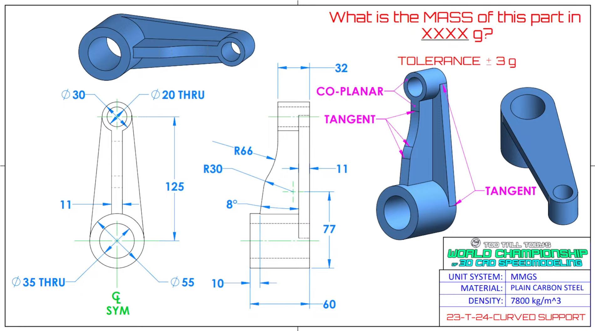
I don't say it's impossible but I believe it's quite near to impossible for most of OpenSCAD users to model this relatively simple drawing[1]. It's a breeze in CAD with constraint solver. Also it's viable in code-first systems with access to shape coordinates (build123d) using only construction geometry and projections. OpenSCAD requires hard trigonometry and math skills to pull it out.
OpenSCAD has amazing community though and part libraries celebrates human ingenuity despite tool restrictions.
This does not match the drawing. In addition it only took 4 minutes to do it correctly in a normal CAD package [1]. OpenSCAD is cool, but it's not at all a replacement for traditional 3D CAD and I wish people would try to sell it on its strengths instead of selling it as a replacement for traditional CAD.
OpenSCAD is really neat! It comes at the model representation process in a very different way.
In it's current form, it will never replace CAD as we know it today.
People have a hard enough time breaking an object they can see into features they can draw and combine, or modify as is done today. Add in the need to work with 2D drawings, sketches, photos, and it gets a bit harder for them still.
I have been training people to use CAD since the days of serious transition away from drafting boards. Very few of them would be able to author the descriptive text examples up thread.
And to be fair, parametric CAD, with or without history is powerful, but hard enough for plenty of people to really struggle, but that difficulty seems a couple orders below what we are discussing here.
Frankly, a better developed OpenSCAD could become a very powerful tool to be used in tandem with traditional CAD. It could even make use of the mature geometry kernels that way too. Those make more complex object and feature create actually work well because they have solutions for the almost innumerable corner and edge cases which always come up.
It is possible to create things largely OpenSCAD style in some CAD programs too. NX has a variety of programming interfaces, one being essentially Visual Basic with CAD appropriate functions.[2] (NX SNAP, as I recall)
You get entity create, query, rename, transform (full transform, scale, translate, rotate), modify like adding a fillet to an edge, boolean cut, join, intersect, split, add, partition... and a whole lot more! (It may not support partition, but it is supposed to for SDRC compatability, and that isn't the point anyway, so... yeah)
And there is the general purpose programming environment. Useful in all the obvious ways we here know well.
The main point is one can take an entirely analytical approach to model create, while also having the robust 3D and on NX 3D stereo[1] even, GUI to evaluate, debug, and all the other good CAD stuff!
To me, that is the OpenSCAD strength. The team can take a peek at the tools I just mentioned, add features and Open Cascade will do way more geometry cases than people think, and now you have model and entity create that can really work for some tough use cases:
--catalog parts with conditional features
--simulation and or analytically driven model shapes, many of which could be used as base features to be finished into manufacturable things
--coupled with an LLM trained on geometry, could result in Star Trek like plain language model create
There is more.
But the actual engineering, product design and manufacturing use cases are not going this way at all. It is too obtuse. People need to see, and I would argue benefit from haptics for interrogation, assembly and more.
Don't get me wrong here. All the open CAD tools are awesome. Open CAD is important and we just don't have much yet, and more is better. We do not have much yet because CAD is really hard, and the robust, mature geometry kernels out there have gazillions of man dev hours in them. Open Cascade is actually quite impressive to be for how well it really does work Given the tiny fraction of dev hours it has by comparison.
And what this means is CAD inertia is a problem likely an order harder than say the replace C code inertial some feel is worth doing.
Best bang for the dev hour investment us to augment and compliment traditional CAD, IMHO of course!
[1] All you need is a stereo capable GPU and display. I used my laptop with nVidia Quadro series and a fast Samsung 3D plasma TV for huge stereo modeling. Frankly, it was crazy good for evaluating technical surfaces and complex, think airplane internals, assembly was down right fun! Recommended and I am unsure why this is not more widely done.
[2] I used SNAP to convert bitmaps into voxel objects, where each voxel was a cube, and from those, combine them into larger voxel objects that were the basis for tooling models to make the desired shape. The retro pixel look you are picturing was desired and I wish I could show the finished project. Neat!
Have also used it to make plenum and manifolds driven by simulation output or area / flow equations.
Both cases would be torture using the traditional CAD model create UX. OpenSCAD is aligned well here if you ask me.
    r1, r2 = 55/2, 30/2
    cd = 125

    # construct rib profile, start with slope and oversized arc
    # reposition line to be constrained on arc center height and Y axis
    l = build_line(O, op_line(-8, 30, name='l1'), op_arc(30, -90, name='a1'))
    l.move(Vector(77-r1*2, 0) - l.a1.center_point)
    ip, = intersections(l.l1, Axis.Y)
    l.move(Y(50 - ip.Y))

    # Now we know first arc center and could project it on a second arc center
    # axis with known distance and get tangent point. Use point to trim oversized fist arc
    # and create second tangent arc.
    a2c = point_on_axis_with_dist(l.a1.center_point, Axis.X.offset((0, 66+32)), 66+30)
    ip, = intersections(l.a1, axis_from_points(l.a1.center_point, a2c))
    l.append(op_trim(ip), op_arc(to=(a2c.X, 32)), XA(cd-r1), YA(0), (l.s.X, 0)).close()

    # Convex hull of base cylinders would have correct tangents
    base_sk = make_hull((X(cd) * Circle(r2) + Circle(r1)).edges())

    # Contruct final part
    obj = extrude(X(r1) * RX(90) * l.face(), 11/2, both=True) + extrude(base_sk, 11)
    obj += Cylinder(r1, 60, align=A.d)
    obj += X(cd) * Cylinder(r2, 32, align=A.d)
    obj -= Cylinder(35/2, 60, align=A.d)
    obj -= X(cd) * Cylinder(20/2, 32, align=A.d)
It took 15 minutes and I used my helpers to aid rib profile construction. With stock build123d it's quite a chore.
This was my impression with build123d and Cadquery.
On paper they have a better abstraction than OpenScad. Yet, the code to express the same output is more bloated.
I was never able to get over the yak shaving learning curve to be proficient. Openscad mental model is a lot simpler to sustain momentum to go build something.
How did you get around to prefer Cadquery/build123d?
> Yet, the code to express the same output is more bloated.
But it's trivially ready to be parameterized and reused. Model is easy to change, you could think about relations between features not absolute entities.
It's my 3rd attempt to use code-CAD to be honest. OpenSCAD -> CadQuery -> Build123d. I have past experience with SolveSpace and OnShape. GUI CAD approach with drafting in 2D and making solids as late as possible works perfectly well and you could transfer spatial thinking as-is to model coding.
I have somewhat frustrating experience with OpenSCAD and CadQuery. OpenSCAD is perfect for simple things but gap to complex parameterized models was to big for me. CadQuery looks great in examples, but I could not grasp how to use it for my tasks. State tracking is crazy hard.
There are three major factors it clicked for me with build123d.
First is explicit algebra mode. My little coder brain could not comprehend large object trees from OpenSCAD or hardcore chain dance of cadquery. But I know what an object and mutability are. Build123d is amazingly intuitive and has tight primitive set large enough for complex things and small enough to be memorized by heart. Also Build123d has nice docstrings and type hints. I mainly use IDE help instead of online docs.
Second is a good interactive visualizer. I use yet-another-cad-viewer[1]. It allows to quickly debug issues and use my favorite editor. It's crucial to have visual representation and ability to know object bindings to variable name in source code. Killer features for me are on-hand access to per-object transparency setting and selection tool to measure distances between features. It really helps during learning.
Third is I actually sat down and spent around 10h with TTT practice models[2] :))
I believe I'm already effective with Build123d on the same level as with OnShape.
There is a major weak thing with code-CADs though. It's edge selection for fillets. I think about custom filters to narrow edge location. But now it's largely a guess work with edge visualization on fail.
Looking back at your build123d code, it looks like the biggest differentiator compare to OpenSCAD and CadQuery is the expressiveness to assign shapes to variables, right?
I was able to check that box with PythonSCAD thus far, so that's "solved" for me.
Otherwise, I see a lot of vector/coordinate manipulation that isn't too different from OpenSCAD/PythonSCAD.
However, I can see there's some additional abstraction primitives with arc and tangents that looks nice. That doesn't quite exist in any OpenSCAD based or similar engine since there's no built-in way to get info out of the shapes in a reflection-like way.
Maybe I will give Build123d another go and see if I can sustain some sort of momentum.
I appreciate your attempt and time spent. It's an amazing showcase how simple things could be easily expressed in OpenSCAD. But the part in question sadly is not that simple. All tangents are wrong.
Erh? Are you complaining about some minor adjustment, so that lines are not meeting the curves smoothly? I did not even understand what TANGENT means, cause I know much nothing about CAD.
I've overlaid your part on the correct part (as best I can when working with the mesh files that come out of OpenSCAD). Your part is drawn in red: https://i.imgur.com/12y5q1t.png
Yes. Lines should touch circles in a smooth way. There could be many arguments why it's kinda important. Like fit to other parts in a final assembly or production complexity. But even for DIY purposes this minor adjustments would suck a lot of blood in prototype phase, it's a way more simpler to constraint it to be smooth (tangent) and forget about all tweaks needed after dimension changes.
You absolutely don't need to get into the maths to get value from this idea. The maths terrifies me. Just know this core concept: a tangent line meets a circle only once and is at right angles to the radius when it does.
Here's why this is valuable in CAD environments that properly support it: once you know how a tangent line works, and see how a constraint-based modeller represents them, it is possible to understand how to model a whole set of smoothly rounded features that the CAD package can automatically adjust to changes made to core measurements, retaining this perfect "join". Rounded slots, curved rounded slots, fillets, all sorts of interesting motion components, etc.
This is good -- but they aren't quite the same? [0]
And the way they are not the same is (as the GP is saying) rather telling about the challenge of getting really precise things working in OpenSCAD without a pretty solid grasp of maths.
[0] they might be functionally equivalent in application, which is not nothing, of course
Couldn't let it go, but got everything except for the positioning of the small radius and maybe the height of the web slope is off (had to increase 2 to 2.05 to keep a gap from appearing).
I think if one laid out the radius stuff flat and then rotated it things would be easier to visualize.
The best thing about the challenges from 3d CAD Speedmodelling is that they needed a quick way to validate submissions, so they do it by validating the mass of the design. The density to use is included in the problem. The answer is on this page: https://build123d.readthedocs.io/en/latest/tttt.html#t-24-cu...
For people interested in coding CAD in React, my team built a react fiber layer over jscad and are investing heavily into building an MIT-licensed 3d electronics library: https://github.com/tscircuit/jscad-fiber
I don't think you need a custom language to declare CAD, typescript/python have heavily invested in type systems so I hope the world moves more toward using existing languages.
The biggest limitation with code-CAD today is the lack of a constraint system (e.g. a clean way to say "these edges are 3mm apart") without X/Y coordinates everywhere. We're slowly building higher-level components that allow you to specify constraints so that you can write CAD in a way that more closely mimics the design intent, rather than a bunch of calculations.
OpenSCAD started it all so we're very grateful, but it's also time for some innovation to bring the language closer to design intent
I've been using jscad for years. Love it, still using it actively almost every day. I also use React/JSX every day for work and personal projects. That said, I'm not sure I like the mash-up of jscad-fiber after taking a look at the github page. Maybe it just doesn't fit my use-case of building several complex parts that have to interface with each other. I'm sure there is a use case for it though. It doesn't seem like jscad-fiber supports things like measureBoundingBox or any lower level stuff. There's a lot of depth to jscad, it's an amazing project.
For those who are interested. I have been working on a similar CAD Modeler. I think of it as a spiritual successor to OpenSCAD.
It has support for bidirectional modeling (ex: get the height and width of an object and use it later) and multi part workflows to design more complex works.
TBH I am not sure but I suspect the answer is yes. I use OpenCascade as the base CAD kernel and it handles things like Z-fighting a lot better. I built DSLCAD after completing porting OpenSCAD to wasm because I wanted a better programmatic CAD platform. It's development is really "as I need it" from then on.
I work out of a local Hackerspace here in Austin and we happen to have one of the core contributors to OpenSCAD here. He re-wrote much of the code in C++ to optimize the core algorithms and significantly improve performance using OpenGL.
He is actively looking for gig-work or potentially something more significant, so if anyone on HN is looking to get something 3D-cad related or even some advanced training, please reach out to me (email is on my profile). I will happily make an intro.
OpenSCAD is an ideal tool for adding flexible 3D wizardry to a website or app programatically.
I ran into rendering limitations when modeling a multi cyclonic add on for my shop vac, and manifold saved this project. I used one of the nightly builds for this.
OpenSCAD has been great for simple projects. It’s very easy to get productive with if you know basic programming concepts. However, I’ve run into frustrating limitations on more complex projects. The core geometry engine is skittish.
I still use OpenSCAD, but I’m diving into the OCCT ecosystem. It has a steeper learning curve, but seems to be significantly more robust.
I think if you want to do complex things in OpenSCAD, you have to use someone's library or write your own.
For example, I wrote centering code that basically work for arbitrary length, which then become a frequently used part of the codebase. Then when I faced the limitation of the centering code, I wrote more code for arbitrary subdivision of elements.
I haven't extracted the new arbitrary subdivision of elements out into a module for my library, but I will eventually.
I've made a bunch of stuff in OpenSCAD and it can be really nice to work with but... it does have a bunch of weirdnesses like not being to find the size of a compound object, having to micro-manage your objects to avoid the spinning beach ball render, fillets/chamfers/rounded edges/etc. are dark arts, etc.
If you're basically sticking simple shapes together or cutting simple shapes out of other shapes, it's fine enough.
I have an openscad-alike that supports fillets/chamfers, but unfortunately getting it to support importing any third party file formats (DXF, SVG, STL) is a bit beyond me right now.
I'd also love to find the time to rewrite the geometry kernel in something like taichi (python DSL running on GPU) or maybe JAX instead of numpy. And of course it doesn't yet pass most of openscad's test cases.
Last January I offered a course on OpenSCAD in my university, perhaps the first one in Brazil or even in Portuguese. The lectures are available here (but it's in Portuguese, perhaps someday I'll translate it to English...): https://lucasoshiro.github.io/posts-en/2024-03-24-openscad/
As cool as OpenSCAD is, it's just one way of writing code to work with CAD.
The commercial CAD systems all have APIs to do the same kind of stuff, but they also have sophisticated UIs on top to make them easier to use visually. NX even lets the user record UI interactions as a function to make creating initial code faster.
In fact, there's a whole niche of CAD programming.
I made macros for Solidworks and Catia v5 during my Mechanical Engineering days and Visual Basic for applications + most Windows program is so powerful. But at the same time, VBA can be such a painful language because some language behavior is not typical.
I bought into Plasticity in the hope that it would gain such facilities, but the dev said that that sort of thing was being pushed off to v3.
Tried Dune3D and was moderately successful, but couldn't see where in the U.I. such numeric/programmatic access would be afforded and it doesn't seem to be on the roadmap there either.
I suppose I should break down and buy Rhino 3D and use Grasshopper, or Moment of Inspiration and use its Node Editor, but for now, I've been using:
> This is a sign that the software has grown to become its own operating system. They also have to add their own version control… remote editing, etc.
Not really, though most of the commercial CAD systems are comparable in size to an operating system already. NX just spits out the journal file, it's assumed the dev will take the code and modify it to their needs using their normal dev workflow and their own version control, IDE, etc..
I've never been comfortable drawing or drafting with GUIs. This is true for "drawing" graphics, laying out boards, or building 3D models for printing or CNC. OpenSCAD has been invaluable to me.
Usually, I'll hand draw what I need, then work out the equations, then build the models. No need to figure out what certain icons mean or to learn accelerator commands. I've built some fairly intricate designs with OpenSCAD. CSG is quite intuitive.
You might like the PCB constraint system we're building at tscircuit for laying out boards, the biggest issue with most systems imo is that you can't cleanly specify constraints. In tscircuit you can just use a <constraint /> component to lay out PCB elements
A few years ago I worked with some fellow artist to design a rubiks cube around a large steel ball bearing using OpenSCAD. We machined the pieces out of aluminum (using a sweet 5-axis mill) and glued magnets into them. https://vimeo.com/322284709
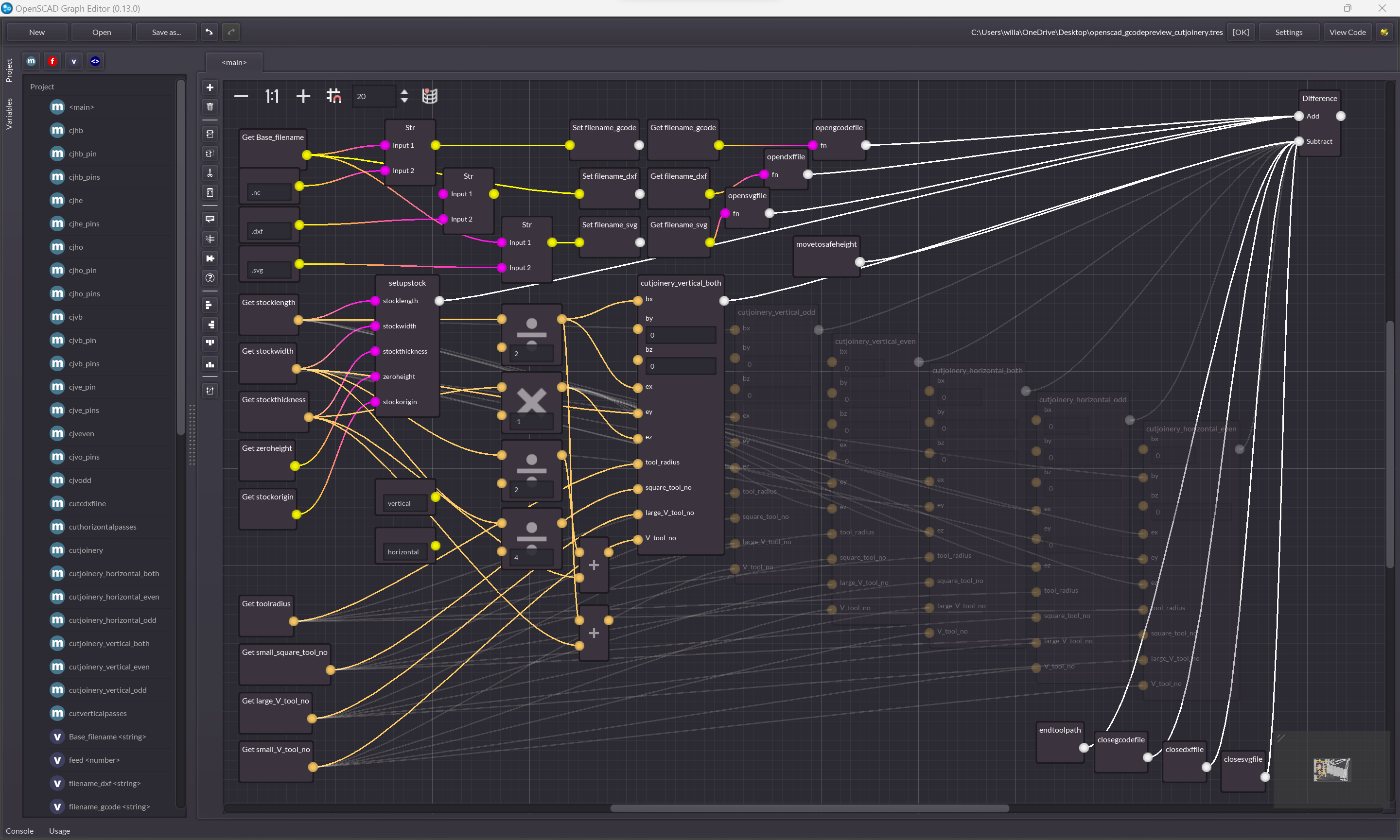
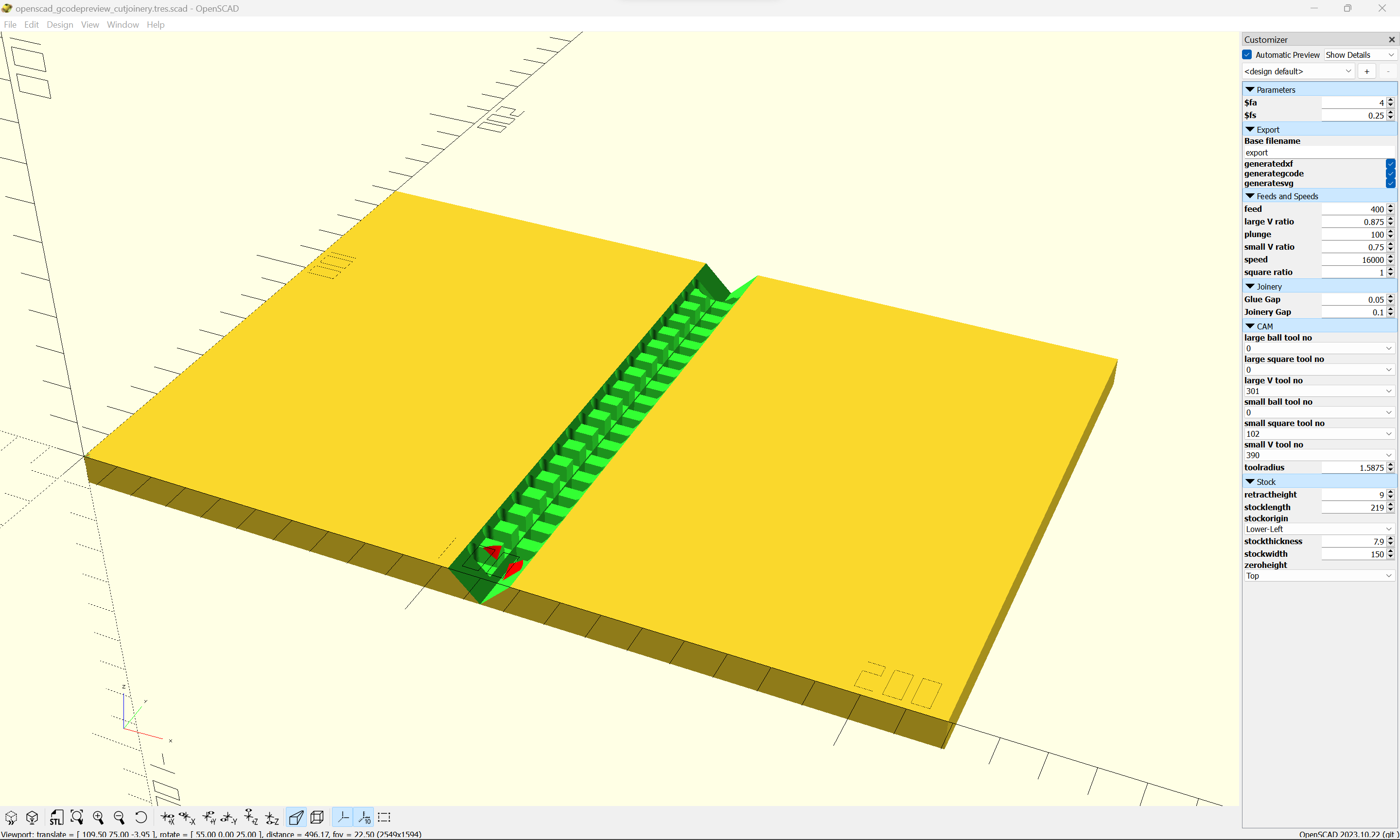
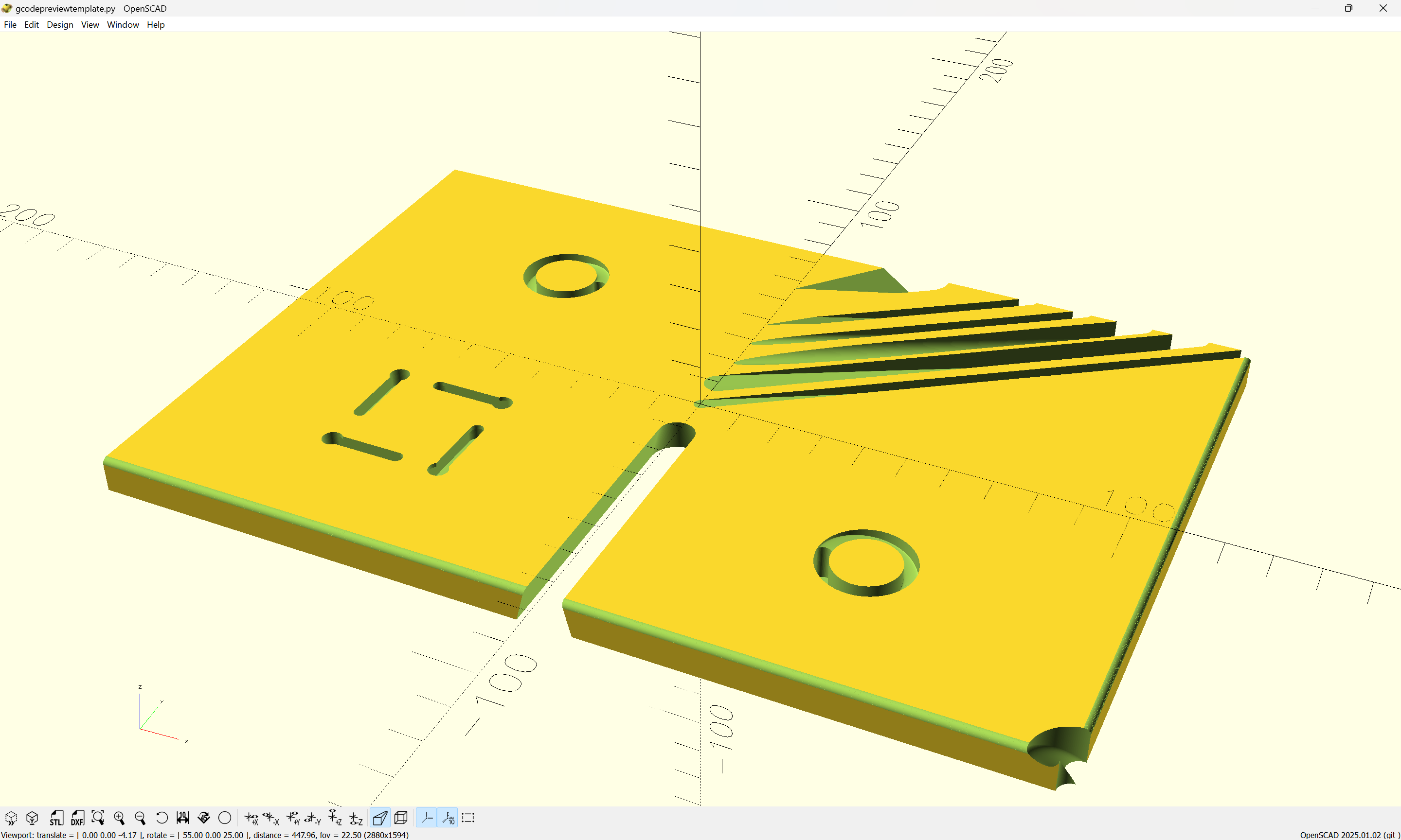
which finally made it possible for me to finally have the ability to write out G-code (allowing one to use OpenSCAD as a CAM tool) and DXFs (allowing one to have fully control and to create not-closed/unconnected geometry, and to write out arcs rather than only polylines):
Yes, it’s a wonderful tool. This post kind of upset me; it’s comparing totally different classes of program.
SolidWorks is subscription based, so your $50 buys access this year and probably you won’t want to use the model again next year, right?
OpenSCAD is free software, and that matters.
Hopefully readers know it’s decades behind and very rough to use. Your example of “superpower modern CAD” could have been a whole lot simpler... probably some simple 2D geometric construction would be enough to show a big gap.
SolidWorks is locked to Windows - out in the real world that might be 95% of the users but here it’s probably 50%.
To finish my defense of OpenSCAD: there’s a place and an upside to all-text source and coding parameterized with traditional variables that you can change in your editor and recompile just like any other code. No GUI is only 80% bad.
First of all, I'm sorry I upset you! That was definitely not intended.
I'm not comparing the two, I want to show what's possible. I often see people finding OpenSCAD, getting comfortable with it because it's all code, and stopping there. But there's so much more to solid body modelling, it's not too complicated to learn, and a bit more advanced CAD really expands the range of physical objects we can create! This is why I chose those slightly more complex examples, I'm not trying to gotcha OpenSCAD, I tried to show why one might want to branch out, despite all the downsides (subscription, non-code source files, Windows*, etc) you mentioned.
Fwiw I dream of a good open source CAD that syncs code and GUI (like KittyCAD) but doesn't fall into the trap of "procedural" modelling like OpenSCAD or KittyCAD. The combination of sketches+constraints+3D operations+projections is perfectly representable as code, it's just much more work than raw CSG, requires a geometric kernel, and is more mind bending. Still, I hope we will get one some day.
*: it does run perfectly well in Parallels though, so between Mac and native Windows I suspect it's more like 80% here
You had me tricked into thinking Solidworks was $50/year.
I was about to impulse purchase a license and switch over from Fusion. That would be an incredibly attractive hobby license and would probably take a lot of money from Autodesk.
There's a difference between noncommercial and barely commercial; if you model something on OpenSCAD and sell a single copy for $5, is that commercial? Lawyers say yes. But no amount of productivity from Solidworks will make spending $3000/year be worthwhile here.
Solidworks says noncommercial but then gives you $2000 leeway on commercial use before you need a commercial license. I’m not sure how they square that with later saying the watermarked files you’ve created don’t work in a commercial version.
And it leaves you with an awkward gap where you sell $2000 and need a commercial license, but even ignoring income tax you don’t have enough revenue to afford that license.
Imagine being new to the CAD landscape. There are so many technologies, and approaches. Different resources talk about the merits of the individual techs.
I would rather someone just flat-out tell me that OpenSCAD etc is ineffective for most projects compared to SolidWorks, Fusion etc; save the trouble of finding out the hard way. Your points are all great, but I don't mind the post you're replying to for this reason.
I'm a big fan of OpenSCAD. I first used it to model a Wii Wheel sort of thing that I could put an Apple TV remote in. But my main use of it was creating a few dozen cars for a video game. Really great fun to model things. If you know CSS and HTML you know enough to create a 3D model in next to no time. https://blog.gingerbeardman.com/tag/openscad/
OpenSCAD of course is not as powerful as other tools, but it has a lot of pros (depending on what you consider a pro):
- Free, unlike other tools such as Fusion or SolidWorks
- Open Source, unlike other tools such as Tinkercad or OnShape
- 100% based on a programming language: compared to others is like comparing plain HTML with HTML + JS
- Parameterizable (as a consequence of being based on a programming language), makes it a lot easier to adjust the model in a second iteration
- Lightweight (it runs ok in my 12 year old desktop)
- It can be used in CLI to generate STL files, makes it easier to automate the model generation
But of course it has a lot of cons:
- It isn't multithreaded, so, it doesn't matter if you have an 32-core CPU or a single core. It also doesn't matter if you have a GPU. So, there's no "best machine" for running it
- You can't compute the size of a shape, unless you know a formula for it. It's specially bad if you are dealing with texts, as you can't predict their shapes unless you're using a monospace font
- It has some bugs in visualization
- Even though it's on active development (you can see that in their Git), its latest release was in 2021
Multi thread support is an experimental feature available on nightly build (and needing to be enabled). The bug tracking it is interesting to read, it has been a long journey... https://github.com/openscad/openscad/issues/391
> But of course it has a lot of cons: - It isn't multithreaded, so, it doesn't matter if you have an 32-core CPU or a single core. It also doesn't matter if you have a GPU.
FWIW these don't have massive benefits for CAD modelling either. Most CAD kernels, even commercial ones, are sort of stubbornly single-threaded.
Sure, multi-threading can really help make the wider application feel more responsive, and a GPU is enormously useful for high-level photorealistic rendering as an end product. But it doesn't bring that much to bear on geometry solving, and the kind of 3D you need for CAD modelling and viewing is pretty old hat in OpenGL terms, I think?
- re-setting the text using METAPOST embedded in LuaLaTeX so as to write out an SVG
- reading the SVG back into OpenPythonSCAD
Bailed when it looked as if the latter step would require using Inkscape to convert to paths (at that point it seemed it would just make more sense to do it all in Inkscape)
Nice! Great to see (Open)PythonSCAD listed! (I know this sort of thing is hard to keep up with --- I was trying for a long while on the old Shapeoko wiki (see link elsethread)).
(below has been edited to reflect my reading the entire page)
A tool which I didn't find and thought wasn't included is:
We used openSCAD in college for our 3D printing class. I think it was a good introduction to modeling in a 3d space since you really have to know what you're doing and the math you want to do, especially for CS majors. But, making anything complex in it is a GIANT pain.
Once we got past the few introductory assignments we were allowed to chose what we wanted and at that point no one in the class was still using it.
Its great for simple things but you'll find it tedious for anything complex, unless of course you like the challenge
OpenSCAD is amazing, especially for highly detailed geometry. Fusion360 was crashing when I modelled a honeycomb structure of ~2000 cells, while OpenSCAD easily handeled a similar model.
OpenSCAD feels awesome to start with, but is ultimately a disappointing experience because it lacks parametric solver capacity; data flow is one way, from the script, to shape generation, to CSG operations, and you cannot do quite reasonable things like extracting dimensions from a CSG-constructed shape and feeding them back into the script.
A better system would enable true constraint-based parametric design, but I think doing so would involve an order of magnitude more complexity in the implementation, and quite probably infeasable compute times.
What are people's thoughts on CAD generation with LLMs for OpenSCAD and other proprietary GUI-based softwares? I imagine soon we will also be able to "autocomplete" or "semantically edit" feature trees in SolidWorks, Fusion, etc.
The problem with most CAD tools is they don't represent "design intent" or high-level components well, and I believe this is mostly due to the language's not being sophisticated enough
e.g. a human says "these holes need to be separated by 2mm", but when we program in OpenSCAD and other CAD languages we usually specify x={-1} for one component and x={1} for the other (just an example of how design intent is being lost)
When we can represent design intent well, we'll have something that LLMs can really grab hold of and build higher level components
> e.g. a human says "these holes need to be separated by 2mm", but when we program in OpenSCAD and other CAD languages we usually specify x={-1} for one component and x={1} for the other (just an example of how design intent is being lost)
What you mean there is constraints, I suppose?
And yes -- there's some work to add constraints to CadQuery sketches/cqparts, but it's early.
I suppose the logic has always been that if you control the placement of parts in code, you can build your own quasi-constraint logic to make reactive, parametric designs. And you might argue that "having complete control over this in code" is its own kind of "design intent" with its own potential justifications.
Specifying constraints in the way the CadQuery development does may not be natural.
But both CadQuery and Build123D have kernel-based tools like face finders, vertex finders etc., that are capable of things that OpenSCAD definitionally cannot do at kernel level.
Replicad (a JS OpenCascade environment) has face and vertex finders, face-based sketching, etc.
i always thought I'd love openscad, being from a more coding background, but it turns out I'm not too fond of it. I eventually used freecad after watching some YouTube videos when I needed to make something.
I'm wondering why I appear to be in the minority questioning how this is news and why it was shared?
I've been noticing a general increase in low effort link shares of, what I consider to be, well known projects. These shared links contain no news or anything that appears to be related to updates or recent development, just links to home pages of relatively popular projects.
At this point, there are 138 comments, which, as is often the case on HN, are much more informative than the link itself and show that the topic is hardly worn out. If it was, it wouldn’t have made the front page.
There hasn't been a release in 3 years and no news updates in 2 years until the recent GSoC announcement. Modern linux distros are still shipping a version from 2021 on a older version of Qt, unless you get a nightly unofficial release from the snap store. That's not a great sign even if there are commits happening. I used OpenSCAD a lot in college and I really hope it has a future. I'm glad to see it's getting sponsors now.
I understand that but a project can still be active even if there are no releases. A lot of software doesn't even get published as packages in distros.
The new Manifold library is blindingly fast for most things --- even things which bring the previous renderer to its knees complete in a reasonable timeframe for Preview(ing), though Render(ing) can require a measurably long wait.
As impressive as NopSCADlib and BOSL2 are (and OMG they are, when you consider what they have to work with!), OpenSCAD is a one-way, declarative CSG environment that essentially only outputs mesh formats. It's really not that much better than working with three-dimensional pixels. You won't really be able to analyse, iterate over or measure your models, easily build on faces, do easy chamfers or fillets, export STEP files, make use of constraint-based designs, model assemblies, or so many other things that "CAD" means in the 21st century. All the tools that help you do this on OpenSCAD are layers and layers of task-specific hacks and clever bodges.
I totally get wanting to make models with version-controlled text files instead of GUI CAD (which can be a sort of weird battle to learn for a programmer), and I get wanting to avoid FreeCAD. I just don't really get wanting to limit oneself to such a limited concept of a 3D "model"!
The three alternative systems I mention are all based around bindings to (or in Replicad's case, cross-compilation of) OpenCASCADE, which is a bRep CAD kernel capable of much richer interactions. It is not without its faults, but arguably code-CAD spares you from some of the inscrutability that trips up FreeCAD's interactive model.
reply